Why a printed part is never exactly to size
A printed part always deviates slightly from its model. Understanding where these deviations come from lets you anticipate them rather than simply put up with them. In FDM, the main causes are:
- Bead width: the deposited material flattens and overflows slightly. Outer contours tend to grow, while holes tend to shrink.
- Thermal shrinkage: the plastic contracts as it cools. PLA shrinks very little; ABS, ASA and nylon shrink more, often around 0.5 to 1% depending on the geometry.
- Faceting: a circle exported with too few facets becomes a polygon, whose inscribed diameter is smaller than expected.
- The "elephant's foot" effect: the first layers, squashed onto the build plate, bulge out by a few tenths of a millimetre.
- Layer stepping: on the Z axis, a dimension can only be resolved to the increment of the layer height (0.1 to 0.3 mm).
In resin, light over-curing around exposed areas produces a comparable effect: holes and clearances close up slightly. UV post-curing can also cause a slight amount of shrinkage.
Expected precision by technology
Before sizing a clearance, you need to know the realistic precision of the process. The values below are rough orders of magnitude for parts a few centimetres in size; they get worse on larger dimensions.
| Technology | Typical precision | Smallest reliable clearance | Remarks |
|---|---|---|---|
| FDM (0.4 mm nozzle) | ±0.2 mm | ~0.2 mm | Undersized holes, XY / Z anisotropy |
| SLA / MSLA resin | ±0.05 to 0.1 mm | ~0.1 mm | Very fine detail, risk of merging clearances that are too thin |
| SLS / MJF | ±0.2 to 0.3 mm | ~0.3 to 0.5 mm | Powder trapped in clearances that are too tight |
For a detailed look at the characteristics of each process, see our guide to 3D printing technologies. The material matters too: PETG or nylon forgives a tight fit better than a rigid, brittle PLA — see how to choose a 3D printing material.
Clearances to plan for by type of fit
Clearance is the dimensional difference between two parts that fit together. Here it's given as total clearance (difference in diameter or width), for a well-tuned FDM printer with a 0.4 mm nozzle. In resin, you can generally halve these values.
| Type of fit | Desired behaviour | Indicative FDM clearance | Example |
|---|---|---|---|
| Tight (press-fit) | Force-fit assembly, no disassembly | 0 to 0.1 mm | Bearing, pin, magnet |
| Just sliding | Hand assembly, no perceptible play | 0.2 mm | Fitted lid, guide |
| Free sliding | Smooth movement, slight play | 0.3 to 0.4 mm | Hinge pin, drawer |
| Loose | Easy assembly, visible play | 0.5 mm and above | Print-in-place parts, coarse joints |
These values vary from one machine to another. For a critical part, the only reliable method is testing: print a clearance test plate, a small plate with several holes or grooves stepped by 0.1 mm, in the same material and the same orientation as the final part.
Apply the clearance to only one of the two parts, preferably the one that's easiest to modify (often the female part). If you split the clearance across both, you risk forgetting it or doubling it during a model revision.
Holes, shafts and orientation
Vertical and horizontal holes
A vertical hole (axis perpendicular to the build plate) usually comes out 0.1 to 0.3 mm too small in FDM. A horizontal hole (axis parallel to the build plate) also suffers from layer stepping and a "ceiling" that sags slightly. Two common solutions:
- design the horizontal hole in a teardrop shape (pointed top at 45°) to avoid overhang;
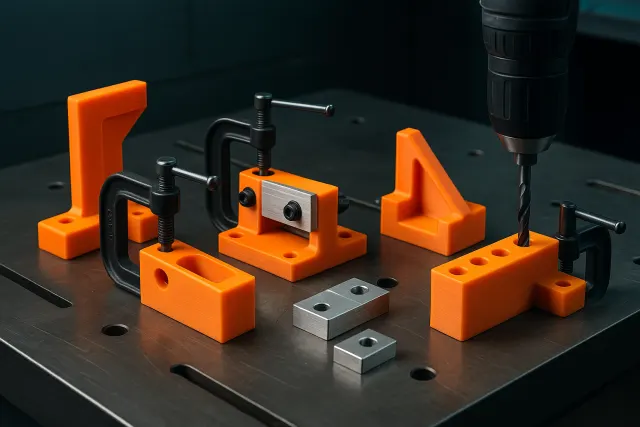
- print the hole slightly undersized and finish it with a drill or a reamer: this is the most precise method for a fine fit.
Orientation and strength
A clip or a tab that flexes must be oriented so the bending happens within the plane of the layers, never perpendicular to it: otherwise it breaks the first time it is loaded. A shaft printed standing up is fragile in shear; a shaft printed lying down is stronger but less round. For heavily loaded shafts, a metal rod inserted into a printed bore is often the best solution.
Threads, screws and inserts
Several options exist for assembling printed parts with screws:
| Solution | Holding strength | Repeated disassembly | Implementation |
|---|---|---|---|
| Self-tapping screw directly into the plastic | Decent | Low (a few cycles) | Pilot hole ~80–85% of screw diameter |
| Printed thread | Average | Average | Reserved for coarse pitches (M8 and above, or dedicated threads) |
| Nut embedded in a hexagonal recess | Good | Good | Recess with 0.2 to 0.3 mm of clearance |
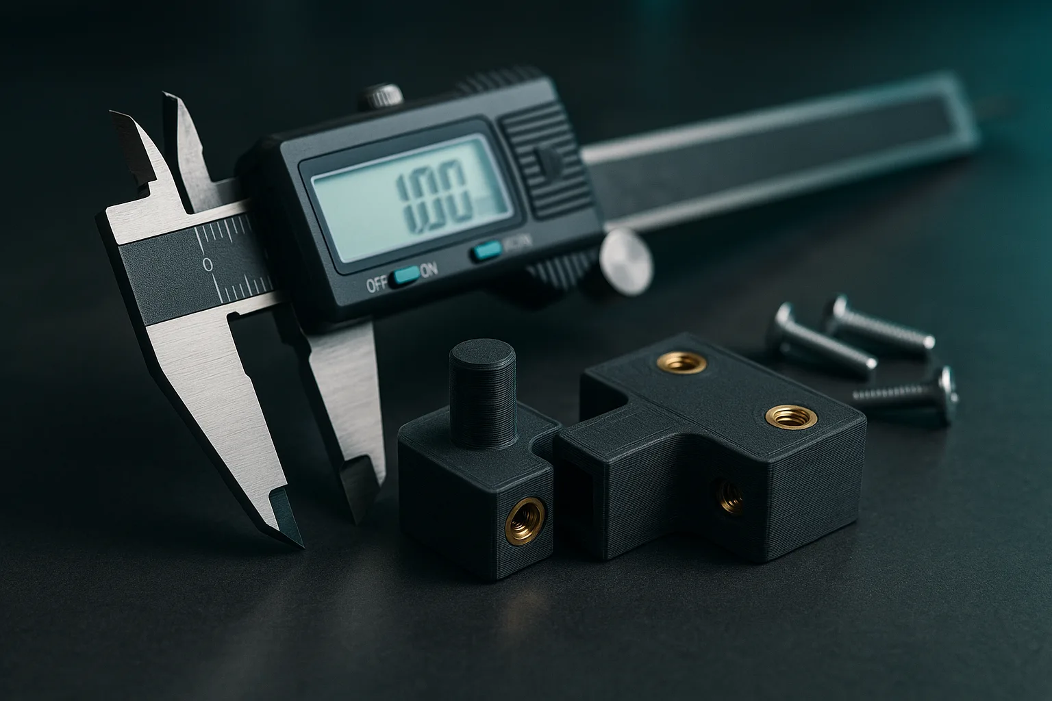
| Heat-set brass insert | Very good | Very good | Hole at the diameter recommended by the manufacturer, installed with a soldering iron |
Heat-set brass inserts are the professional solution in FDM: they are pressed in hot into a slightly undersized hole, the plastic melts around the knurling and re-solidifies. Allow at least 1.5 to 2 mm of material around the insert and a hole depth greater than the insert's length to collect the displaced material. These techniques are widely used for workshop jigs and tooling.
Joints, clips and print-in-place parts
- Clips: give the tab enough length (at least 5 to 10 times its thickness) so it can flex without breaking, and prefer PETG, nylon or sintered PA12 over PLA.
- Dovetails and slides: chamfer the entry points and allow 0.2 to 0.3 mm of clearance per face.
- Print-in-place hinges: allow at least 0.4 to 0.5 mm of clearance in FDM, more in SLS/MJF so the powder can escape.
- Large assembled parts: add centring pins and a bonding surface, rather than a simple edge-to-edge joint.
If you are designing in parametric CAD, define the clearance as a variable: you will be able to adjust it in a second after testing. This is one of the advantages described in our article parametric model or mesh. For a file that is already ready, also check the points in our guide to preparing an STL or 3MF file.
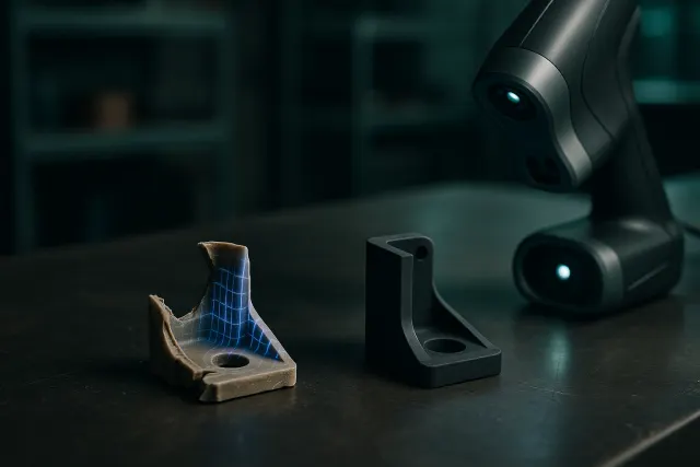
When reproducing a part that fits into an existing assembly, measure the receiving part rather than the old, worn-out one. A precise 3D scan of the surroundings avoids a lot of back-and-forth; our workshop has an industrial scanner accurate to within 0.1 mm, and you can request a 3D scan.
Checklist for a successful assembly
- Identify the functional dimensions: bores, hole spacing, joint thicknesses. Other dimensions can stay at the process's standard precision.
- Choose the type of fit for each connection: tight, just sliding, free sliding or loose.
- Build the clearance into the model, on a single part, rather than relying on a slicer setting.
- Export with sufficient resolution so circles stay round.
- Print a test piece in the final material and orientation if the fit is critical.
- Plan for finishing work: holes to ream, faces to sand, inserts to install, and leave the necessary material.
- Flag the critical dimensions to the workshop, with the expected tolerance, so it can adapt the orientation and settings.
Finally, note that the AI 3D Studio lets you adjust a generated part's parameters with sliders, including its joint dimensions, before ordering the print. For replacement parts, our guide to 3D printed spare parts complements this approach.
Frequently asked questions
What tolerance should you plan for a joint in 3D printing?
In FDM with a 0.4 mm nozzle, allow about 0.2 mm of total clearance for a just-sliding fit, and 0.3 to 0.4 mm for free movement. In resin, half of that is usually enough. The most reliable method remains printing a clearance test piece in the same material.
Why are 3D printed holes too small?
The deposited material overflows slightly toward the inside of contours, and exported circles are polygons whose inscribed diameter is smaller. The result: an FDM hole often comes out 0.1 to 0.3 mm too small. Make it bigger in the model, or finish it with a drill.
What is the precision of a 3D printer?
A well-tuned FDM printer commonly reaches ±0.2 mm on parts a few centimetres in size. Resin printing goes down to ±0.05 to 0.1 mm. SLS or MJF powder sintering sits around ±0.2 to 0.3 mm, and precision gets worse on larger dimensions.
How do you fix a screw into a 3D printed part?
For a few assemblies, a self-tapping screw in a pilot hole is enough. For frequent disassembly or high tightening torque, use a nut embedded in a hexagonal recess or a heat-set brass insert. The insert offers the best holding strength in FDM.